Sub Surface Turf Irrigation Drip Zone Planning 2

Sub Surface Turf Irrigation Drip Zone Planning 2


Drip Zone Planning For Sub Surface Drip Irrigation Systems

Now that we have gone over the basics for Drip Emitter Tubing and Flow rates we will apply this to a sample sub surface drip system.  For this example we will assume the following:

  • 240 gph flow rate available
  • 50 psi
  • We will use Techline DL with a .42 gph emitter output rate and 12" spacing between emitter.

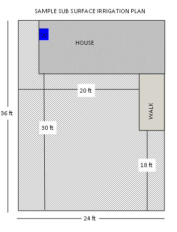
The illustration below will serve as our sample property for the installation of the sub surface system.

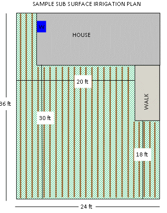
We will now illustrate our Drip Line layout ove our property sketch to calculate our Drip Line requirements and Water Requirements for the system.

Drip Line Calculation:

3 x 36   = 108

16 x 30 = 480

5 x 18   = 90

Total     = 678 ft

Water Requirement:

Since our Drip Emitter Tubing is spaced at 12" we will have 678 emitters each with an output of .42 gph so our water requirement for the entire yard is calculated as follows:

678 Emitters  x .42 GPH/Emitter = 271.2 GPH

At this point we can see that if we are using a .42 gph emitter flow rate we will not be able to water the entire system at one time and will need to split the sytem into two zones as our water available is 240 gph and we need 271.  That being said we always recommend to be conservative with water estimates and never plan for more than 75% of water available, which would make our available flow 203.4 gph (271.2 x 75%).

Planning Alternatives

As we noted above our sample system will need to be split into 2 zones, however depending on the the variables you are presented with the same layout two zones can be avoided.

Drip Emitter Output: If we were to reduce the emitter output to .26 gph the water requirement for the system would then be 176 gph (678 emitters x .26 gph/emitter).

Flow Rate Available: If our flow rate availabe had been 400 gph we also could have avoided the need for two zones.  However we must also keep in mind that this would require the use of a 3/4" supply header to the system as a 1/2" poly tube has a maximum flow rate of 240 gph.  

We will now continue with our 2 zone assumption to illustrate the system, however the connections and layout are virtually identical to that of a one zone system if our assumptions had changed. 

<<Previous Page         Next Page>>


Ref 1031